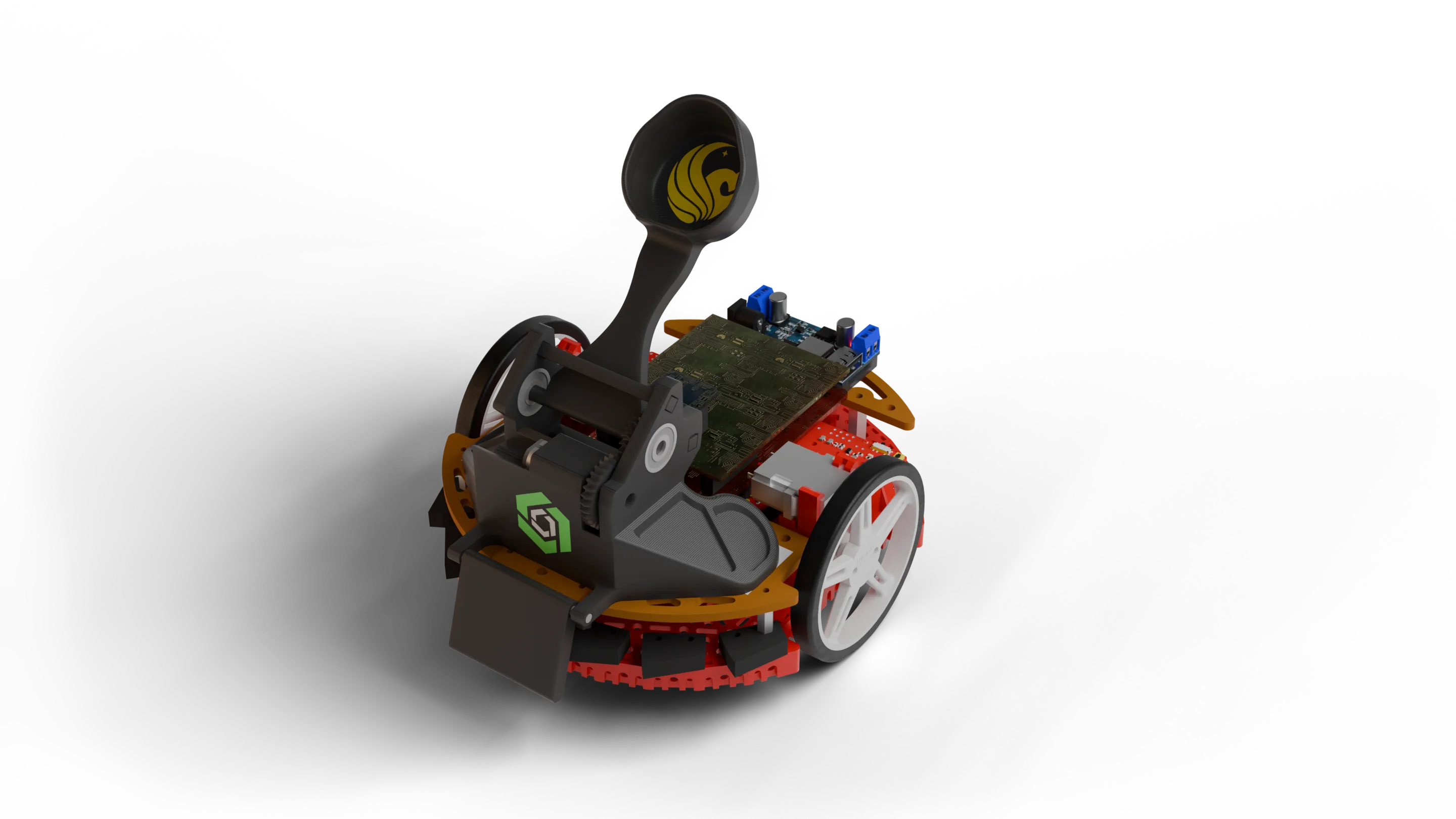
Duck Launcher Final
At UCF every freshman engineering student is split into groups of four and tasked with designing and programming a TI-RSLK robot to score as many little rubber ducks in the “pond” as fast as possible by following a black line to the pond within 10 minutes.
The pond is a large pentagon in the middle of 5 tracks that teams are trying to score into. There are 3 zones in the pond, each getting progressively smaller and worth more points; 100, 300, and 500 respectively. There are also penalty cups closest to the black line that add a time penalty if hit, and bonus cups at the start line that can be hit on the way back for a 50 point bonus every time.
Design
Our main design goal was to score in the 500 point section as quickly as possible. We really wanted to get cycle times to be as quick as possible since we were worried about the small size of the center 500 point ring filling up and preventing us from scoring all the points possible. Some constraints we had to follow were that the robot must be against the pond wall before shooting a duck and the motors on the robot were rather weak, making it essential we keep the weight of our mechanisms to a minimum. We also needed to hit the wall perfectly perpendicular to make aiming more accurate.
After testing out several design archetypes we settled on a motorized lever arm. This allowed us to quickly shoot ducks as soon as we hit the wall of the pond and was overall a very lightweight and compact mechanism. To fix the aiming issue we added a front bumper that went over the front two bump switches that forced the robot to go flat against the wall. We ended up going through seven versions, tweaking various gear ratios and arm lengths before we finally settled on the model we used. Here is the link to the CAD for anyone interested: CAD Model - Onshape
Programming
Every group was provided with very basic but working example code. However, this code was very messy and extremely slow which caused me to decide to rewrite it from scratch. One of the biggest issues with the example code is that they do not use a full PID, instead they just use a P value. While this works fine for the majority of robots, if you wanted to go faster than about 30% speed a true PID implementation is required.
State Machine Architecture
I structured the program around a state machine with six states: START, RESTART, PATH, SHOOT, TURN, and DONE. This made the code significantly cleaner and easier to debug which I will give credit to the example code for doing partially correct. Each state has its own dedicated function that handles exactly what needs to happen in that phase of the run.
The robot starts in START, waiting for a button press. Once triggered, it transitions to PATH where the line following happens. When the bump sensors detect the wall, it moves to SHOOT, fires the duck launcher mechanism, then enters TURN to do a 180-degree spin. After turning, it goes back to PATH to return home. On the second bump which is hitting the robot resetters hand for faster reset times, it transitions to DONE and waits for a restart by pressing the front bumper again.
Full PID Implementation
A proper PID controller is needed to consistently follow the line at faster speeds. The key improvement over the example code was using actual time deltas for the integral and derivative calculations rather than assuming a fixed loop time. We tuned our constants to KP = 0.05, KI = 0.001, and KD = 0.01 which allowed us to run at 90% motor speed while still tracking the line accurately. These values differed per robot as they all were in different states of disrepair so we were never able to tune the PID to be as smooth as I wanted.
float dt = (currentTime - lastPIDTime) / 1000.0;  // Convert to seconds
int error = linePos - GOAL;

float P = KP * error;
integral += error * dt;
integral = constrain(integral, -1000, 1000);  // Anti-windup
float I = KI * integral;
float derivative = (error - lastError) / dt;
float D = KD * derivative;

float motor_speed_delta = P + I + D;
The integral term includes anti-windup clamping to prevent it from accumulating too much error when the robot is off the line for extended periods. We also reset the PID state (error, integral, and timing) whenever transitioning between states to prevent any weird behavior from stale values.
Shooter Control
The shooting mechanism was very simple, just a digital pin that triggers a relay to trigger the motorized lever arm. A quick HIGH pulse for 300ms is all it takes to launch a duck into the pond. I added small delays before and after to ensure clean activation and so that we don’t brownout the robot which was an issue we had when trying to run both the wheels and shooter motor at the same time.
The full code can be view here on my github: DuckLaucher
Its not very pretty as a good bit of it was redone the day of the competition for a slight optimization in the PID. There is also a very basic score keeping webpage, its only slightly broken.
Retrospective
Overall we did great and I’m very proud of my team for coming first out of over two thousand freshman engineers! The average score was probably less than 2-3k which we crushed, scoring 30,500 points with 81 ducks (44 in the 500, 24 in the 300, and 13 in the 100).
There were a lot of cool and unique designs that I saw and we learned a lot about what works and what should be avoided. If we were to do this again there are several things we would change.
First off, our fears of the center getting filled were confirmed, but not due to other teams—our cycles were so fast that the center was filled about 2-3 minutes into the competition. This caused a lot of ducks to bounce out of the center off of other ducks and land in the 100 and 300 point sections. We had nearly perfect accuracy so all the ducks from the score breakdown in the other sections are due to them bouncing out of the center. The best way to avoid this would probably be to fine tune the launch angle so that it either goes at a more downward angle to bounce up again or go at a very shallow angle so that the ducks hit the back wall of the 500 point zone and bounce inwards. This is similar to what our launcher did but it could be improved. Another way could be instead of launching the ducks, have a way to drop or place them in the center which would prevent them from bouncing out and make it so they can be stacked higher before completely filling it up.
Second, the PID tuning process could be improved. Ideally the PID should be tuned on a straight line at the weight of the final robot, and even better with the robot that is going to be used during the competition. Realistically the latter isn’t possible but the first two are very achievable and I am annoyed I didn’t think to just bring electrical tape to the lab and make a straight line for tuning.
The last thing is the line sensor is so close to the wheels that the PID needs to have higher than normal values to compensate for the short response time that’s needed. This isn’t as essential since we were able to run at 90% speed and most likely could have gotten that higher with more time spent tuning, but if it’s possible to move the line sensor forwards then do so.
A fun bonus tip is to 3D print or buy a second wheel for the robot as they normally only had one and it makes it significantly more stable and accurate.
Video of our competition
Links: